Fibre optic starry ceiling
7 mistakes to avoid before installation
From choosing the light engine to planning fibre routes: the checks to carry out before installation to coordinate components, site preparation and the final lighting effect.
In this article
Creating a fibre optic starry ceiling requires coordination between lighting design, component selection and preparation of the suspended ceiling.
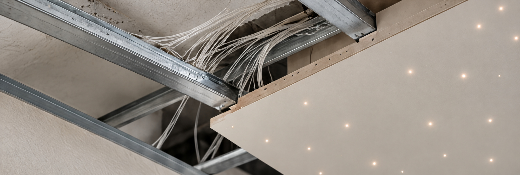
The system includes a light source, known as a light engine, a fibre optic harness and a common connector, which couples the harness to the light source. Light travels along the fibres to the ends visible on the ceiling.
The arrangement of light points, fibre diameters and lengths, and light source specifications must be defined together. Here are seven mistakes to avoid before installation.
7 MISTAKES TO AVOID
Failing to provide accessible space for the light engine
The light engine must be installed in a space that accommodates its overall dimensions, connections and the operating conditions specified by the manufacturer.
This check must also include the connector and the harness outlet. A unit that fits inside the ceiling void may still be difficult to connect or remove.
An access hatch or equivalent access must be provided. Even fanless models require the specified installation conditions to be met for adequate cooling.
Sizing the harness without checking the fibre routes
The fibres, or tails, branch out from the common connector to reach the individual light points. Their lengths must be determined according to the actual route through the ceiling void.
The distance from the light engine, obstacles and changes of direction can affect the route. Another factor to consider isoptical attenuation, the reduction in light as it travels along the fibre.
Setting the density without planning the star arrangement
The light point density, expressed as the number of points per square metre, describes how densely the surface will be populated. On its own, it does not define the visual effect.
You must also determine the spatial arrangement: irregular to evoke a natural sky, or organised into constellations and predefined patterns.

Precision makes the difference
The light point layout and fibre routes must be defined together with the position of the light source.
Overlooking diameter and minimum bend radius
The PMMA synthetic monofilament fibres, made from polymethyl methacrylate, are available in various diameters, selected according to the intended result.
During installation, you must observe the minimum bend radius: the specified limit for bending the fibre while staying within the manufacturer's stated conditions.
| Fibre | Outer diameter | Minimum bend radius |
|---|---|---|
| FB750 | 0.75 mm | 5.25 mm |
| FB1000 | 1 mm | 7.00 mm |
| FB1500 | 1.5 mm | 10.5 mm |
These values apply to the products listed. For other fibres, consult the relevant documentation. View COBB technical specifications .
Choosing the light source based on wattage alone
The electrical power, expressed in watts, is not enough to determine which light engine to use. Compatibility with the harness, the type of light and the required effects must also be assessed.
The COBB range includes white light sources, RGB+W and models with a twinkling effect. Dimming, colour changing and integration via DMX, DALI or Casambi depend on the model and configuration.
The LRGBW-LED15-TW, for example, uses RGB+W LEDs, incorporates a twinkling effect and supports control via an RF remote, an app and a DMX signal.
A professionally installed system
Access, routing and the sequence of work must be coordinated before closing the suspended ceiling.
Confusing fibre characteristics with the unit's protection rating
Fibres carry light without carrying electrical current to the light points. The light engine, however, remains an electrically powered unit with its own installation requirements.
The IP protection rating applies to the unit's enclosure and must be assessed in relation to exposure to solid objects and water.
This is the rating specified for the LRGBW-LED15-TW model. The second digit, zero, indicates no protection against water ingress: the unit must not be considered waterproof.
Failing to coordinate drilling, installation and finishing
The sequence of work affects fibre handling and the finishing of the light points.
In COBB's plasterboard installation procedure, the fibres are inserted from the back of the panels and initially left protruding. The finishing of the fibre ends is carried out after painting and drying.
What to prepare before installation
To assess the system and coordinate installation, gather the following information:
- A plan and dimensions of the surface to be illuminated.
- The type of substrate and the space available in the ceiling void.
- The position of the light engine and access to it.
- The planned fibre routes.
- The light point arrangement and the desired effect.
- The control methods and environmental conditions.
For installation, refer to the documentation supplied with the system and the installer's checks.
Your starry ceiling starts with a plan.
COBB Fibre Ottiche designs and manufactures bespoke systems. Share the details of your space to define the fibres, light source and desired effect.