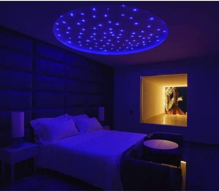
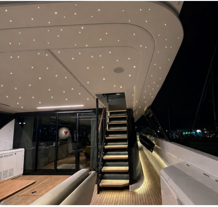
FROM DESIGN TO COMPLETION
A starry ceiling begins with a design
How we manufacture our fibre optic systems.
System quality, from design to completion.
01 / COBB FIBRE OPTICS
A system is more than a collection of components
Quality comes from the way the parts work together. The light source, optical coupling, bundle and distribution of light points must all follow the same design.
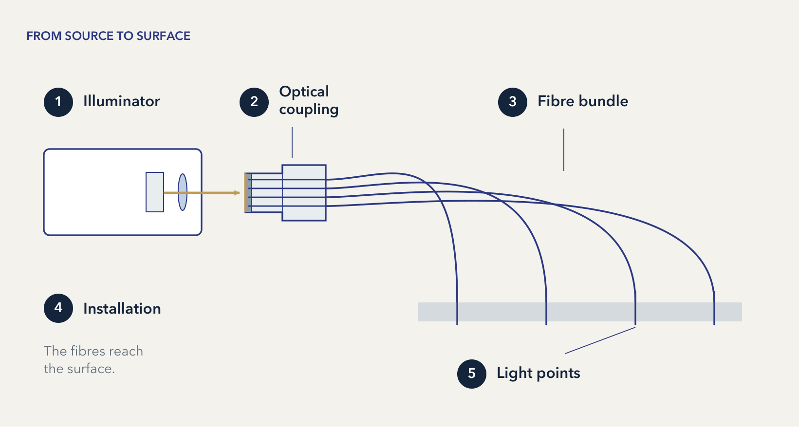
Light, input and routing
The illuminator generates the light. Optical coupling directs it onto the bundle's input surface. The fibres guide it to their ends, which are visible in the ceiling.
Addressing the details before installation
Bundle preparation and illuminator optics work at the same interface. Preparing this interface during manufacture addresses issues that could otherwise require adjustments after installation, adding time and cost.
02 / COBB FIBRE OPTICS
Design comes before light
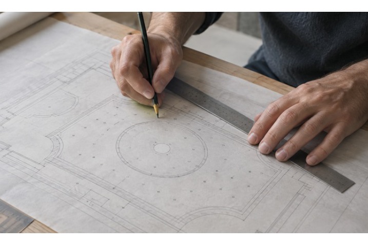
COBB Fibre Ottiche designs and manufactures bespoke fibre optic lighting systems, from starry ceilings to museum, residential and marine applications. Each solution starts with the characteristics of the space and the requirements of the project.
- Space and application
- Surfaces, geometry and intended use define the starting point: every setting requires a dedicated solution.
- Distribution
- The design establishes where the light should go. The lighting layout becomes the reference for assembling the bundle.
- Diameters
- Fibre selection is assessed alongside light distribution and the requirements of the specific application.
- Grouping
- Grouping connects the fibres to the common connector. The position of the light source and the fibre routes must be considered together.
- Illuminator
- The type of light, bundle and required control must be consistent with the model's technical specifications and the selected configuration.
Defining these choices before manufacture helps limit adaptations and revisions once work is underway.
03 / COBB FIBRE OPTICS
Light reaches where it is needed; the source remains accessible
In FB synthetic fibres, the core and cladding form a step-index structure. Light enters the core and travels along the fibre through internal reflections.
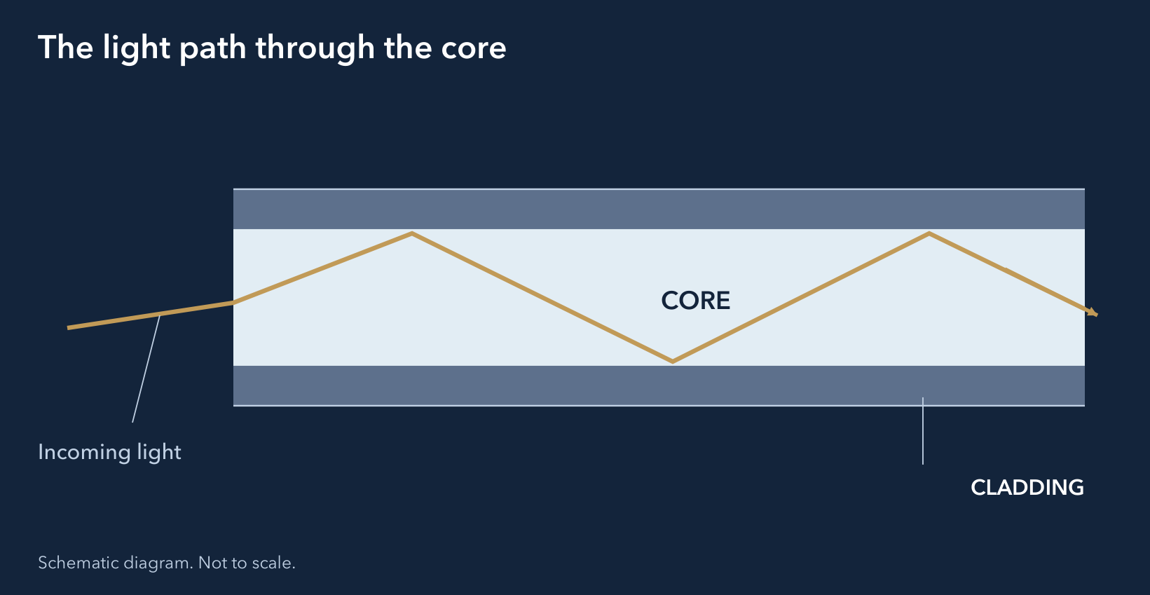
Two materials, one optical function
Core: polymethyl methacrylate (PMMA).
Cladding: fluorinated polymer.
The materials and structure determine how the fibre guides light. Their selection contributes to the system's optical quality, alongside preparation of the input surface.

04 / COBB FIBRE OPTICS
Where the illuminator meets the bundle
Connector quality concerns the interface between the light source and the fibres. Securing, alignment and finishing are addressed during manufacture, before the bundle reaches installation.


- 1. Bundle
- The fibres are gathered and arranged parallel to one another. This arrangement keeps their direction aligned with the axis of the light source.
- 2. Termination
- Cutting and polishing prepare the common end of the bundle. These operations bring the fibres onto an even input plane.
- 3. Connector
- The front aluminium ferrule is mechanically compressed. This securing method is designed to retain the fibres even under torsion and mechanical stress.
- 4. Optical surface
- The flat, polished surface faces the light source at a right angle. This is where light enters the bundle.
05 / COBB FIBRE OPTICS
Precision also comes from manufacturing
This sequence shows how COBB prepares the bundle before installation. Securing, cutting and polishing create the geometry through which the fibres will receive light.
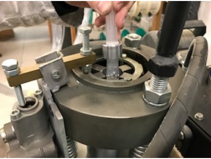
01. Mechanical securing
A dedicated machine compresses the front aluminium ferrule containing the fibres. Mechanical securing stabilises the bundle before the subsequent operations.

02. Cutting the excess
The fibres projecting beyond the connector are cut. Cutting prepares the common surface that will then undergo optical polishing.
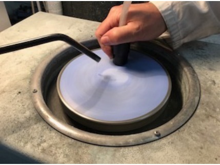
03. Two-stage polishing
Two passes with abrasive paper make the surface flat and polished. This operation prepares the plane where light meets the bundle.
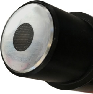
04. Final result
Secured, parallel fibres and a flat optical surface. The bundle faces the light source with the fibres oriented perpendicular to it.
Original photographs from COBB documentation.
06 / COBB FIBRE OPTICS
Directing light into the fibre
Bundle preparation and illuminator optics work at the same point: the fibres' input surface. The lens focuses the LED light towards the common connector.

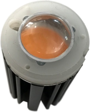
Light meets a prepared surface
The quality of the finish works together with the source optics: the lens directs light onto the bundle, while the flatness and orientation of the fibres prepare the receiving surface.
Preparing both elements during manufacture addresses optical coupling before installation, when a correction would require further work.
07 / COBB FIBRE OPTICS
Light in the ceiling, the source away from it
Separating the illuminated surface from the light source allows accessibility to be considered during design. The starry ceiling layout and the illuminator position are parts of the same system.
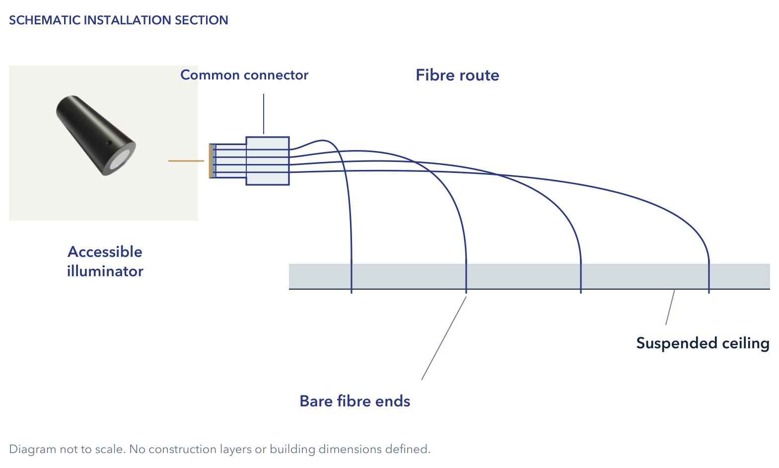
Plan access to the source from the start
An accessible location makes accessibility part of the system design. Addressing it after completion may require further assessment and time.
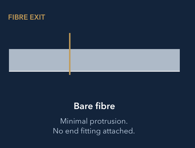
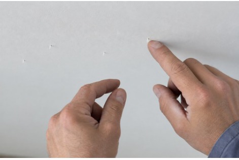
The light point is the end of the fibre itself: a slight projection, with no attached terminal fitting.
08 / COBB FIBRE OPTICS
An accessible, maintainable system
Any later intervention involves access, diagnosis and working time. This is why a good design also allows the illuminator to be reached once the surface is complete.
Three parts to consider separately
The surface, fibre network and illuminator have different functions. Their separation makes it possible to plan access to the source independently of the light point layout. Maintainability depends on the access actually provided.
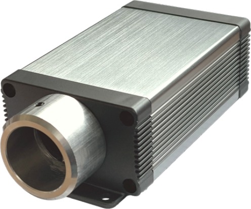
Points to consider during design
- Illuminator position
- An accessible location is essential for technical access. It must be consistent with the bundle layout.
- Fibre routes
- The route connects the source to the lighting layout. Defining it during design helps limit adaptations once installation has begun.
- Indicative lengths
- Lengths depend on the routes and source position. Defining them early resolves a choice that affects bundle preparation.
- Bends and accessibility
- Bends and access spaces are part of the project's feasibility. Permitted values require confirmation from COBB.
- Suspended ceiling
- Adequate space for the fibres allows the planned route to fit within the designed surface.
COBB verification required: lengths, bend radii and routing clearances.
09 / COBB FIBRE OPTICS
Illuminators for starry ceiling systems and the COBB range
The COBB range includes LED, halogen and metal halide light sources. The illuminator, bundle and control method are selected to suit the application.
LED / white light
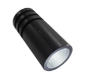
LWH-LED3
White light
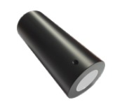
LWH-LED9
White light

LWH-LED10-TW
With twinkle effect

LWH-LED12-DIN
Dynamic white

LWH-LED20-TW
With twinkle effect
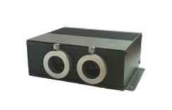
LWH-LED25-TW
With twinkle effect
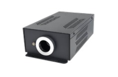
LWH-LED30
White light

LWH-LED30-DIN
Dynamic white
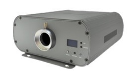
LWH-LED40-TW
With twinkle effect

LWH-LED90
White light
LED / RGB+W
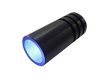
LRGB+W/LED4
RGB+W light

LRGB+W/LED12
RGB+W light
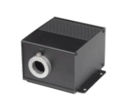
LRGBW-LED15-TW
With twinkle effect
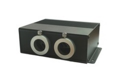
LRGBW-LED30-TW
With twinkle effect

LRGBW-LED40
RGB+W light

LRGBW-LED60-TW
With twinkle effect
Halogen and metal halide
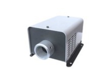
MLA-VR/SN
Halogen
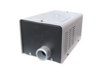
LA-VR/SN
Halogen

LH150-VR/SN
Metal halide
The model follows the design
The type of light, bundle and control are defined alongside the requirements of the specific application.
Choosing the control
Push-button, RF, touch, app, voice assistants, DMX, DALI and Casambi: options within the range whose availability must be checked for the selected model and variant.
10 / COBB FIBRE OPTICS
A complete process
The process addresses decisions that affect the result before installation. The aim is to limit later revisions and adjustments, together with the time and costs they involve.
- DesignSurface, distribution, diameters and source are considered together. The design defines the light point layout and fibre routes.
- Bundle preparationThe fibres are organised to suit the configuration. Grouping and routing connect the surface layout to the common connector.
- ManufacturingSecuring, cutting and polishing prepare the bundle geometry and its light input surface during manufacture.
- InstallationThe prepared system takes shape during installation. Fibres, routes and source follow the choices established during design.
- CompletionThe design becomes visible. The care taken at the start also supports accessibility and any subsequent work.
11 / COBB FIBRE OPTICS
One system, different spaces
In every setting, quality comes from consistency between the design, bundle and source. Spaces and lighting layouts change; the care given to the system as a whole remains.